The first set of combination of angle gauges was devised by Dr. Tomlinson of N.P.L. With thirteen separate gauges used in conjunction with one square block and one parallel straight-edge, it is possible to set up any angle to the nearest 3″. In the same way, as slip gauges are built up to give a linear dimension, the angle gauges can be build up to give a required angle. Angle gauges are made of hardened steel and seasoned carefully to ensure permanence of angular accuracy, and the measuring faces are lapped and polished to a high degree of
accuracy and flatness like slip gauges. These gauges are about 3 inch (76.2 mm) long, 5/8 inch (15.87 mm) wide with their faces lapped to
within 0.0002 mm and s angle between the two ends to ? 2 seconds.
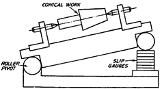
Fig. 8.20. Sine Centre.
The secret of this system in having any angle in step of 3″ is the adoption of a mathematical
series of the values of the angles of various gauges of the set. The thirteen gauges can be divided into three series ; degrees, minutes and fractions of a minute. The gauges available in first series are of angle 1?, 3?, 9?, 27? and 41?. Second series comprises 1′, 3′, 9′ and 27′ angle gauges and this series has 0.05′, 0.1′, 0.3′ and 0.5′ (or 3″, 6″, 18″ and 30″) angle gauges. All these angle gauges in combination can be added or subtracted, thus, making a large number of combinations possible. There are two sets of gauges available, designated as A and B. The standard A contains all the above 13 gauges. Standard B contains only 12 gauges and does not have the 0.05′ angle gauge.
Direct combination enables computation of any angle upto 81? 40.9′ and angles larger
than this can be made up with the help of the square block. However, an additional gauge of
9? can also be supplied with the set to obtain a full 90? angle without the use of the square.
Fig. 8.21 illustrates how the gauges can be used in addition and subtraction. The procedure
used for making various angles is as follows : e.g. say, we have to build up an angle of 57?
38′ 9″.

Fig. 8.21. Angle gauges can be used in addition and subtraction mode.

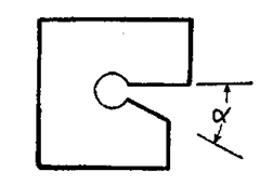
(a) Die insert
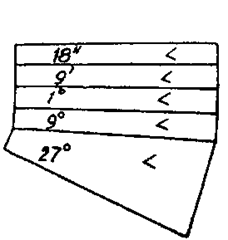
(b) All gauges added. Total angle
= 37? 9′ 18″ (Not to scale)
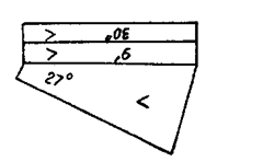
(c) Angle set up = 27? minus
9′ 30″ = 26? 50′ 30″
Fig. 8.22
Thus it is seen that any angle could be made up but the block formed by the combination
of a number of these gauges is rather bulky and, therefore, cannot the always directly applied
to the work. But these gauges being used as reference and taking the aid of other angle
measuring devices will be a good proposal at many places.
Angle gauge blocks seem to lack the requisites for use as primary standards because
errors are easily compounded when angle blocks are wrung in combination. Further the
absolute verification of angle blocks is usually dependent on some other primary standard.
8.7.1.
Uses of angle gauges
(i) Direct use of angle gauges to measure the angle in the die insert.
To test the accuracy of the angle in the die insert, the insert is placed against an
illuminated glass surface plate or in front of an inspection light box. The combination of angle
gauges is so adjusted and the built-up combination of angle gauges carefully inserted in
position so that no white light can be seen between the gauge faces and die faces. It may be
noted that when all the engraved Vs on the angle gauges are in the same line, all angles are
added up. In case some engraved Vs on angle gauges are on other side, those angles are
subtracted.
(ii) Use of angle gauges with
square plate.
As already indicated, the use of
square plate increases the versatility of
the application of angle gauges. Generally,
the square plate has its 90? angles
guaranteed to within 2 seconds of arc.
Where very high degree of accuracy is
required, the four corners of the square
plate are numbered as A, B, C and D, and
a test certificate is issued with each set of
angle gauges, giving the measured angle
of each corner. Fig. 8.23 shows a set up to
test the angle of V-gauge whose included
angle is 102?. The whole set up is placed
against an illuminated glass surface
plate. It may be noted that the use of slip
gauges has to be made in order to
facilitate the testing.
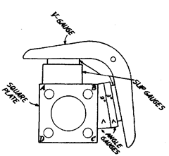
Fig. 8.23. Set-up for checking V-gauge having
included angle 102?.
So far, we have used angle gauges to obtain a visual comparison of an angular dimension
under test. It has also been realised that though it may be possible to obtain good results but
it is difficult to give an estimate of the actual angular error. For very precise angular
measurements, angle gauges are used in conjunction with angle dekkor described later in
Art. 8.10.9.
8.7.2.
Manufacture and Calibration of angle gauges.
First the angle gauge is
approximately machined to the desired shape, hardened by quenching, tempered and
stabilised. The non-gauging sides of the block are then ground to obtain uniform thickness,
and made flat and parallel by
lapping operation. One gauging
face is also lapped flat and made
square to the lapped non-gaug-
ing sides. The simple method
for manufacture of 27? and 9?
angle gauges is described to ex-
plain the principle. This method
requires the use of sine bar tilt-
ing table, slip gauges and mag-
netic chuck. The set up is shown
in Fig. 8.24, in which the sine
table is set at 27? and magnetic
chuck fixed on tilting table sur-
face, and the four 27? angle
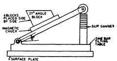
Fig. 8.24. Set-up for grinding 27? angle gauge blocks.
gauge blocks wrung side by side on to the magnetic chuck. Their upper surfaces are then surface
ground parallel to the base of the table, thereby producing four blocks, of exactly equal angle
which are again checked for accuracy of angle. In similar manner, 9? blanks are also finished
and the three 9? blocks are wrung with 27? block in opposite direction so as to form a block
with parallel sides, as shown in Fig. 8.25.
This combination of block is checked for error in
parallelism. Thus error of each 9? block relative to 27? block
will be one-third of the error noted in parallelism of com-
posite block of Fig. 8.25. All the blocks of 9? are again lapped
together till the error in parallelism is equal to the permis-
sible value. In this way, all the gauges would be of equal
angle but not necessarily of 9? and 27? exactly. The actual
error in individual block from its true angle can be got rid
of by the following procedure. Three blocks of 2 7? and one 9?
block are wrung together to form a composite block of 90?
and its squareness is tested by any of the method described
in Art. 7.8.2 and the error noted down. On of the 27? angle
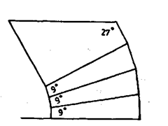
Fig. 8.25. Combination of 3 blocks
of 9? and one block of 27? so as
to form parallel set of blocks.
block is then lapped to reduce its error to zero by making it similar to a standard angle gauge
whose actual angle is known. In this process, the gauge being manufactured (lapped) is wrung
with standard 27? angle gauge and error in parallelism noted and it is further lapped till error
in parallelism becomes zero. Other 27? blocks are also corrected in same way individually. All
the four 27? blocks are then placed on magnetic chuck and it is ensured that the outer faces of
all are in one true plane by lapping them together carefully. Same procedure is followed for 9?
blocks also. Finally 3 blocks of 27? and one block of 9? are again wrung to make a combination
of 90? block which is tested for squareness by autocollimator method as described in Art. 7.8.2.3.
8.7.3.
Calibration of angle gauges by interferometry.
By this method, precision of the order of 0.1″ of
arc in angle measurement is possible. It is assumed that
these gauges have high degree of flatness on their working
surfaces. The gauge length interferometer is used for this
purpose. The angle gauge is wrung on the platen carefully
(Fig 8.26). On viewing through the eyepiece, two inter-
ference patterns are seen consisting of straight, parallel and
equally spaced fringes. But due to angle between the two
surfaces, the pitch of the two sets of fringes is different. Let
there be p fringes above the platen and q fringes above the
gauge on same length I.
Then 8 = 0! ? G2 = X (p-q)/2l
where K is the wavelength of light used. There is however a
limitation that angle upto only one minute can be measured
directly by this method. Therefore, first the gauges of third series must be inspected and then others by combiiiations
and adjusting optical flat to same angle.
0 comments: