The sine principle uses the ratio of the length of two sides of a right triangle in deriving a given angle. It may, be noted that devices operating on sine principle are capable of ?self generation?. The measurement is usually limited to 45? from loss of accuracy point of view.
The accuracy with which the sine principle can be put to use is dependent in practice, on some form of linear measurement. The sine bar in itself is not a complete measuring instrument. Another datum such as a surface plate is needed, as well as other auxiliary equipment, notably slip gauges, and indicating device to make measurements.
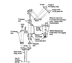
Fig. 8.9. Diagrammatic arrangement of the optical system employed in optical dividing head.
Sine bars used in conjunction with slip gauges constitute a very good device for the precise measurement of angles. Sine bars are used either to measure angles very accurately or for locating any work to a given angle within very close limits. Sine bars are made from high carbon, high chromium, corrosion resistant steel, hardened, ground and stabilised. Two cylinders of equal diameter are attached at the ends. The axes of these two cylinders are mutually parallel to each other and also parallel to and at equal distance from the upper surface of the sine bar. The distance between the axes of the two cylinders is exactly 5 inches or 10 inches in British system, and 100, 200 and 300 mm in metric system. The above requirements are met and maintained by taking due care in the manufacture of all parts.
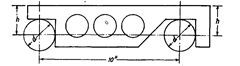
Fig. 8.10. Sine bar.
The various parts are hardened and stabilised before grinding and lapping. All the working surfaces and the cylindrical surfaces of the rollers are finished to surface finish of 0.2 [im Ra value or better. Depending upon the accuracy of the centre distance, sine bars are graded as of A grade or B grade. B grade of sine bars are guaranteed accurate upto 0.02 mm/m of length and A grade sine bars are more accurate and guaranteed upto 0.01
mm/m of length.
Although there are several forms of sine bars, but the one shown in Fig. 8.10 is most commonly used. Some holes are drilled in the body of the bar to reduce the weight and to facilitate handling.
However, from the point of view of ease in manufacturing to ensure an exact distance between the cylinders, the form shown in Fig. 8.11 is preferable. Also this type of sine bar can be set to a steep angle without the slip gauges fouling the underside of the bar. But this point is immaterial as the accuracy of setting appreciably decreases with steep angles and from the point of stability also we generally do not use sine bars for steep angles.
Before using any sine bar for angular measurement work, for accuracy and precision, it is better to ensure whether the following accuracy requirements and tolerances as specified by I.S. 5359?1969 for 100 mm sine bar are met with :
Characteristics Permissible Tolerance
Flatness of upper and lower surfaces 0.001 mmParallelism of upper and lower surfaces w.r.t. datumsurface when resting on it 0.001 mmFlatness of side faces 0.005 mmSquareness of side faces to upper surface 0.003/25 mmParallelism of side faces to the axes of rollers 0.01/25 mmFlatness of end faces 0.003 mmSquareness of end faces to the upper surface 0.003/25 mmParallelism of end faces to the axes of the rollers 0.01/25 mmStraightness of individual rollers and freedom from lobing anduniformity in diameter 0.002 mmMean diameter of rollers 0.002 mmDistance between the roller axes ? 0.003 mm
Roller axes:
(i) In a common plane over the length of either roller 0.003 mm
(ii) Parallel to and equidistant from the upper surface over the length of either roller 0.003 mm.
Flatness of the bearing surface of the setting foot 0.003 mm Various types i.e., different designs of sine bars required for different applications are shown in Fig. 8.10. Fig. 8.11 also shows the nomenclature of sine bars as recommended by IS : 5359?1969.
As already pointed, sine bar shown in Figs. 8.10 to 8.14 is more preferred form as the distance between the rollers in this case can be adjusted exactly. This type of sine bar can be easily set on steep angle without the slip gauges fouling the underside of the sine bar ; of course, the accuracy of setting decreases with steep angles.
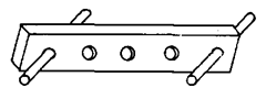
Sine bar shown in Fig. 8.12 is most commonly used form in which the rollers are so arranged that their outer surfaces on one side are level with the plane top surface of the sine bar.
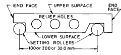
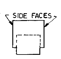
Fig. 8.11
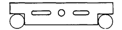
Fig. 8.12
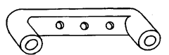
Fig. 8.13
1 comments:
the figure is not so clear, are there any references with the figure a little clearer?